I. Why the need for four-terminal measurement
In precision current measurement, we are faced with a problem that cannot be ignored:contact resistance. When shunts are bolted or soldered into circuits, contact resistance occurs at the connection points, and this additional resistance can lead to measurement errors.
Taking a typical 100 μΩ shunt as an example, if the contact resistance at the connection point is 2 μΩ (which is common in practice), the error reaches 21 TP3T - which is totally unacceptable for applications requiring 0.51 TP3T or even 0.11 TP3T accuracy.
Kelvin four-terminal technology is designed to solve this problem.
Two, four-terminal measurement principle
2.1 Basic concepts
The four-terminal (also known as four-wire) measurement method separates the current path from the voltage measurement path:
- Current Terminal (Force): For applying the measured current and withstanding the contact resistance and heat generation.
- Voltage Terminal (Sense): Used to detect the voltage drop across the resistive element without passing large currents
2.2 Principle of operation
in a four-terminal configuration:
- The current terminals are connected to the main circuit and the high current flows through the shunt
- The voltage terminals are connected directly to the active area of the resistive element and the voltage drop is measured with a high impedance meter
- Since almost no current flows in the voltage measurement circuit, the voltage drop across the contact resistor is negligible
- The measured voltage reflects only the voltage drop across the resistive element itself, independent of the contact resistance.
2.3 Equivalent circuit analysis
Total resistance for two-terminal measurements = R shunt + R contact 1 + R contact 2
Measured resistance ≈ R shunt for four-terminal measurement (contact resistance excluded)
This allows four-terminal measurements to be more than an order of magnitude more accurate than two-terminal measurements.
Third, the structural design of the four-terminal shunt
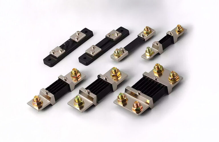
3.1 Terminal Layout
Standard four-terminal shunts typically have the following construction:
- Two large cross-sectional current terminals (usually with screw holes or copper row connections)
- Two small-sized voltage-sensing terminals (usually pin or screw terminals)
- Voltage terminals are located inside the current terminals, near the resistive element
3.2 Voltage Sensing Point Location
The choice of location of the voltage sensing point is critical:
- Should be located in an area of even current distribution
- Avoid close proximity to terminal welding areas (uneven current distribution)
- The two sensing points should be arranged symmetrically
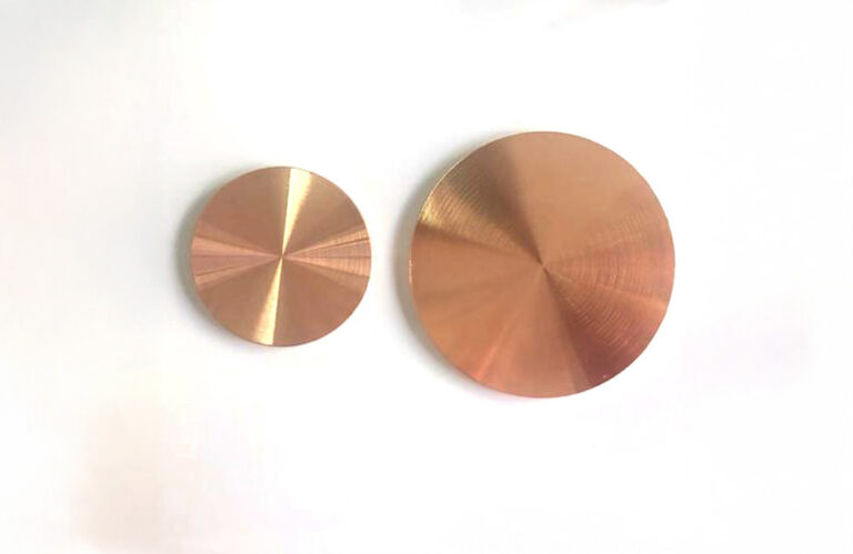
3.3 Materials and Processes
- Current terminals: Purple copper or brass, tin/nickel plated surface
- Voltage terminals: copper or brass, small size design reduces heat transfer
- Resistor element: Manganese copper and other low TCR alloys
- Welding: Electron beam welding or brazing
IV. Application circuit design points
4.1 Voltage measurement circuit
- High input impedance: Op amp or ADC input impedance should be >10MΩ.
- Low bias current: Input bias current should be as small as possible
- differential input: Use of instrumentation amplifiers or differential ADCs
4.2 Wiring requirements
- Separate routing of current and voltage lines
- Shielded twisted pair cable for voltage sensing lines
- Voltage lines as short as possible to minimize pickup noise
- Single-ended grounding of the shield
4.3 PCB Design
- Current paths and sense paths are separated on the PCB
- Sensing alignment is thin to avoid shunting
- Be aware of the influence of the thermoelectric potential and avoid the use of dissimilar metals
V. Common problems and solutions
5.1 Thermopotential interference
concern: Thermoelectric potentials are generated at the contact of different metallic materials and temperature gradients lead to measurement errors.
tackle:
- Use of connecting cables of the same material
- Maintain uniform temperature at connection points
- DC offset elimination using AC excitation or chopping techniques
5.2 Electromagnetic interference
concern: The magnetic field generated by the high current induces a disturbing voltage on the voltage sensing line
tackle:
- Voltage sensing wires tightly twisted
- Keep away from high current conductors
- Reasonable arrangement of the direction of alignment
5.3 Common Mode Voltage
concern: Shunt is at high potential during high side detection, high common mode voltage
tackle:
- Use of differential amplifiers with high common mode rejection ratio
- Adoption of isolated measurement schemes
- Low-side detection (if allowed by the system)
VI. Examples of practical applications
6.1 Battery test equipment
Battery charge/discharge testing requires accurate current measurement to calculate capacity. Using a four-terminal shunt + 24-bit ADC, current measurement accuracy of 0.02% level can be realized.
6.2 Smart meters
Electricity metering requires high accuracy and long-term stability. The four-terminal manganese-copper shunt is the standard solution for smart meters, with an accuracy level of up to 0.2S.
6.3 High Current Power Supply Test
Efficiency testing of switching power supplies, inverters and other high-current devices, four-terminal shunts with precision power analyzers to achieve accurate power measurement.
VII. Summary
Kelvin four-terminal technology is the basis for precision current measurement, effectively eliminating the effect of contact resistance on measurement by separating the current path from the voltage measurement path. When designing a four-terminal measurement system, attention needs to be paid to details such as terminal layout, wiring methods, PCB design, etc., while guarding against problems such as thermal potential and electromagnetic interference. The correct application of four-terminal technology can improve the accuracy of shunt current measurement to 0.1% or even higher, meeting the stringent requirements of energy storage, electric vehicles, metering and other fields.