Introduction: the centrality of current detection in a BMS
With the booming development of the global new energy vehicle industry, Battery Management System (BMS) has become a key technology that determines the safety, range and service life of electric vehicles. As one of the core functions of BMS, accurate current detection directly affects the accuracy of battery state estimation (SOC), state of health evaluation (SOH) and state of power prediction (SOP).
In power battery systems, current detection needs to cover a wide range from milliamps to kiloamps, while maintaining high accuracy measurements in harsh temperature environments ranging from -40℃ to 85℃. This technical challenge has given rise to the development and competition of a variety of current detection solutions, with shunts and Hall sensors being the two most dominant technology routes in the market today.
I. Technical requirements for BMS current detection
1.1 Precision requirements
According to GB/T 38661-2020 "Battery Management System Technical Conditions for Electric Vehicles", BMS current detection accuracy should reach ±1%FS (full scale) or higher. However, the actual requirements of OEMs are often more stringent, and some high-end models require the current detection accuracy to reach ±0.5% or even ±0.3%. This is because the current integration is one of the main methods for calculating the SOC, and even small measurement errors accumulated over a long period of time can lead to significant SOC deviation.
1.2 Dynamic response
The battery current of an electric vehicle can change rapidly under operating conditions such as rapid acceleration and energy recovery. For example, during emergency braking, the energy recovery current may jump from 0A to hundreds of amps in tens of milliseconds. Therefore, current sensors need to have sufficient bandwidth (typically ≥10kHz) to accurately capture these transient changes.
1.3 Temperature stability
Power battery packs have an extremely wide operating temperature range, from -40°C in cold regions to 85°C in high summer temperatures are required for normal operation. The current sensing element must maintain stable measurement accuracy over the full temperature range, and the temperature coefficient of resistance (TCR) is a key indicator for evaluating this performance.
II. Principles and characteristics of shunt technology
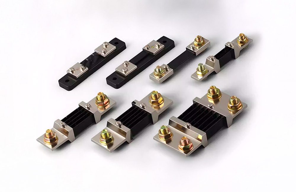
2.1 Principle of operation
A shunt is a current measuring element based on Ohm's law. When current flows through a precision resistor with a known resistance value, a voltage drop proportional to the current is generated across the resistor: U = I × R. By accurately measuring this voltage drop, the value of the current flowing through the resistor can be calculated.
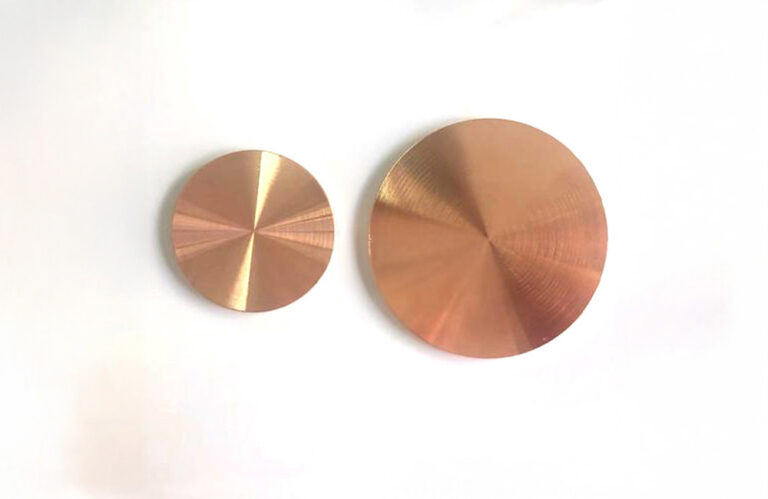
The core of the shunt is a precision resistor body made of special alloys such as manganese copper and con copper. These alloys have extremely low temperature coefficients (TCR can be as low as ±5ppm/°C) and excellent long-term stability, enabling constant resistance values to be maintained under severe operating conditions.
2.2 Advantages of Manganese-Copper Alloys
Manganese-copper alloy (Manganin) is the most commonly used resistive material for shunts, with typical compositions ranging from Cu-12%Mn-2 to 4%Ni. The alloy has the following excellent properties:
- Very low temperature coefficient:TCR can be controlled within ±10ppm/°C in the range of 0~100°C.
- Low thermal potential:Thermal potential for copper is less than 0.5μV/°C, avoiding additional errors in measurement.
- High stability:Annual drift rate can be controlled within 0.01%
- Good machinability:Easy to weld and mold
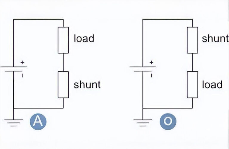
2.3 Application of shunts in BMS
In EV BMS applications, shunts are usually placed at the high voltage negative terminal (HV-) of the battery pack in a low-side detection scheme. Typical shunt resistance values range from 25 μΩ to 100 μΩ to produce measurable voltage drops (typically 50 mV to 150 mV) at high currents while keeping power losses within acceptable limits.
For high precision measurements, shunts are often used with 24-bit or higher resolution Sigma-Delta ADCs. These ADCs have excellent noise rejection and high common-mode rejection ratio (CMRR) to accurately extract small voltage signals on the shunt.
Third, Hall sensor technology principles and characteristics
3.1 Principles of operation
Hall sensors utilize the Hall effect to measure current. When current flows through a conductor, a magnetic field proportional to the size of the current is generated around it. Hall elements placed in this magnetic field will output a voltage signal proportional to the strength of the magnetic field, thus indirectly measuring the current.
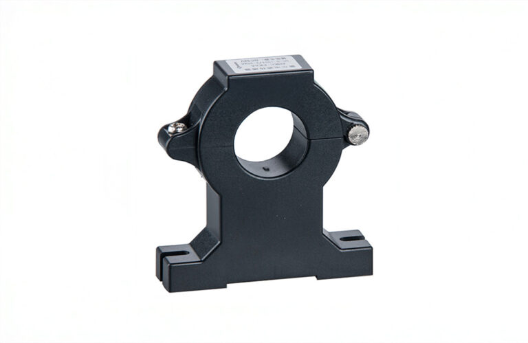
3.2 Open and Closed Loop Hall Sensors
Depending on the mode of operation, Hall sensors are categorized as open-loop and closed-loop:
Open Loop Hall SensorsSimple structure, low cost, but the accuracy is relatively limited (usually ± 1% ~ ± 2%), and is greatly affected by temperature.
Closed Loop Hall Sensors(also known as magnetic balance type) After the magnetic field generated by the primary current is detected, a compensating current is generated by the secondary coil to cancel out the primary magnetic field, so that the magnetic circuit always maintains a zero flux state. This method greatly improves the measurement accuracy (up to ±0.5%) and bandwidth (up to 200kHz), but the cost is correspondingly higher.
3.3 New Magnetoresistive Technology
In recent years, tunnel magnetoresistive effect (TMR) and giant magnetoresistive effect (GMR) sensors have received more and more attention in the field of BMS as a new generation of current detection elements. Compared with traditional Hall elements, TMR sensors have lower temperature drift (up to 0.1~0.2%), higher sensitivity, and lower power consumption, and are expected to replace some Hall sensor applications in the future.
IV. Comparative analysis of shunts and Hall sensors
4.1 Comparison of precision
| parameters | High Precision Splitter | Closed Loop Hall Sensors |
|---|---|---|
| Typical Accuracy | ±0.1%~±0.5% | ±0.5%~±1% |
| temperature coefficient | ±5~±50ppm/°C | ±100~±500ppm/°C |
| annual rate of drift | <0.01% | <0.1% |
In terms of accuracy, the shunt has a clear advantage, especially in terms of stability over a wide temperature range.
4.2 Security and isolation
A major advantage of Hall sensors is the natural electrical isolation that exists between the primary and secondary sides, which is an important safety feature in high-voltage systems. Shunts, on the other hand, are connected directly in series in the circuit and require additional isolation measures (e.g. isolation amplifiers) to achieve signal isolation.
4.3 Power consumption and heat generation
Shunts incur significant power losses at high currents. A 100μΩ shunt, for example, consumes 25W at 500A, which not only affects system efficiency, but also poses thermal challenges. In contrast, the power consumption of Hall sensors comes mainly from electronic circuits, typically only tens of milliwatts.
4.4 Cost comparison
High precision shunts and accompanying ADC solutions are relatively low cost, while closed loop Hall sensors are typically 2 to 3 times more expensive than shunt solutions. This makes shunts more competitive in cost-sensitive applications.
V. Suggestions for selection and development trends
5.1 Selection Considerations
When choosing a current detection solution, engineers need to consider the following factors:
- Accuracy Requirements:High precision requirements prioritize splitter solutions
- Current Range:Consider Hall sensors for very high current (>1000A) applications
- Segregation needs:Hall sensors are more advantageous where electrical isolation is required
- Heat dissipation conditions:Thermal impact of shunt needs to be evaluated when heat dissipation is limited
- Cost budgeting:Splitter solutions preferred for cost-sensitive applications
5.2 Dual Sensor Redundancy Design
With the increasing requirements of functional safety (ISO 26262), more and more BMS are adopting the dual redundancy design of shunt + Hall sensors. Two sensors with different principles can be calibrated against each other to improve the reliability and safety of the system.
5.3 Future trends
Looking to the future, shunt technology will develop towards lower resistance values, higher power density and better temperature characteristics. The application of new alloy materials and advanced welding processes will further enhance the performance boundary of the shunt. At the same time, integrated solutions (such as shunt + ADC + MCU integrated module) will also become an important development direction to simplify system design and reduce the overall cost.
concluding remarks
Current detection technology is the core foundation of BMS, which directly affects the safety and user experience of electric vehicles. With its advantages of high precision, high stability and low cost, shunt occupies an important position in the field of BMS current detection. With the continuous development of the new energy vehicle industry, the requirements for current detection accuracy and reliability will continue to improve, which will also promote the continuous innovation and progress of shunt technology.
Safran specializes in the development and production of high precision shunts, which are widely used in new energy vehicles, energy storage systems and other fields. For more technical details or product selection support, please contact our technical team.